John-Del
2017-06-26 19:02:20 UTC
After owning this about 40 years, I decided to restore it. Doing some Googling it seems there are several model 60 variants with later versions having factory changes done during the run. According to the website http://www.tuberadioland.com/philco60_lineage.html , there are five versions of the model 60 and three sub-versions of the third version which I believe I'm in possession of.
Mine looks like this: Loading Image...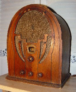
It has the same cabinet/speaker grille shape and the same escutcheon. The website identifies this as a "style three- early version ". This "early version" has a unique escutcheon (like mine), but my knobs look like the later versions. The knobs on mine are exactly like this one: Loading Image...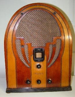 . So mine has the escutcheon of a third version -early and has the knobs of one of the two later versions of version three. Whew.
I suppose it's possible this radio had the knobs changed over the years but they are at least Philco knobs from another 60 if they have been replaced.
The label inside the cabinet identifies it as a "Philco Chassis Type 60 Code 121" and the tube layout chart has "Philco Models 60 & 505" on it.
The radio is in very good cosmetic shape and in beautiful shape below the chassis. Other than a tacked in electro done probably 50 years ago judging by the capacitor used, it *might* be all original and unmolested. The only thing I've done thus far is to take apart the dial drive. I removed the three bearings and cleaned the caked on muck, cleaned the bore and bearing races, repacked it with grease and it works smooth as glass.
My main question though is what to do with the bakelite capacitor blocks. Are these generally left alone unless they need attention or must they be replaced/rebuilt as part of a prudent restoration?
John
Wolcott, CT
Mine looks like this: Loading Image...
It has the same cabinet/speaker grille shape and the same escutcheon. The website identifies this as a "style three- early version ". This "early version" has a unique escutcheon (like mine), but my knobs look like the later versions. The knobs on mine are exactly like this one: Loading Image...
 . So mine has the escutcheon of a third version -early and has the knobs of one of the two later versions of version three. Whew.
I suppose it's possible this radio had the knobs changed over the years but they are at least Philco knobs from another 60 if they have been replaced.
The label inside the cabinet identifies it as a "Philco Chassis Type 60 Code 121" and the tube layout chart has "Philco Models 60 & 505" on it.
The radio is in very good cosmetic shape and in beautiful shape below the chassis. Other than a tacked in electro done probably 50 years ago judging by the capacitor used, it *might* be all original and unmolested. The only thing I've done thus far is to take apart the dial drive. I removed the three bearings and cleaned the caked on muck, cleaned the bore and bearing races, repacked it with grease and it works smooth as glass.
My main question though is what to do with the bakelite capacitor blocks. Are these generally left alone unless they need attention or must they be replaced/rebuilt as part of a prudent restoration?
John
Wolcott, CT
